top of page
Search
  • Writer's pictureChristopher McKinney


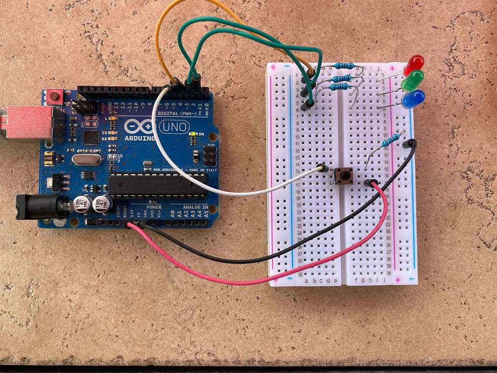
This will be the final blog post on the Circuit Talk website. I hope that all of you viewers have enjoyed the lessons that I have given on how to design circuits, solder, and most importantly, program. As I look back on the progress of my blog, website, and podcasts, I really see how much I have improved in communicating my passions and ideas to a community that is also interested. Since I have been teaching and informing in all of my last blog posts, I thought that I would be appropriate to share the things that I have learned going through this social media process.


The first thing I learned when creating my website is that you want to keep it very minimal and easy to navigate. You don't want to distract your visitors or overwhelm them with too much information. In addition to this, it should also looked really appealing. I was able to make my website appealing by using a good color scheme with the variations of blue and a simple logo.


For social media posts, the best thing to do is post frequently to keep all of your followers updated. This involves letting them know when you release new content, such as blog posts and podcasts on the website. These posts should give a little bit of detail to what the blog/podcast is about.


Finally, for a podcast, it is VERY important that you plan the podcast out beforehand and make a detailed outline of what you are going to talk about. Through the podcasts that I have done. I have realized that trying to talk about a certain topic without an outline is very hard. However, I also recommend not writing word for word what you are going to say. This can make the podcast sound very monotone and uninteresting.


After learning all of these social media and website management skills, I have decided that I am likely going to start my own YouTube channel, going into further detail about all of the circuit projects that I am designing. This will allow me to share my passion with other people that are interested. When I create this channel, I will add the link on this website so it can be accessed. I hope you all enjoyed the blog series and learned something new!

0 views0 comments
  • Writer's pictureChristopher McKinney

Today, I decided to do this blog post outside because of how nice it was today. This blog post will be the last part of our circuit building series and will focus on programming the microcontroller that powered our LEDs (light emitting diodes). This programming language that we will be using is called C++ and is used for many other purposes besides programming microcontrollers. The software to write these programs can be found on Arduino's website, but I would recommend using their online editors for beginners which can be found at the following link: https://create.arduino.cc/editor

So what will we be programming exactly? We will be designing a button that turns on 3 LED's with a single button. While this can be achieved without programming, it is a great exercise for beginners and a fun way to learn the inputs and outputs of the Arduino Uno microcontroller. Here is a picture of what the circuit that we will program looks like:


Once you have a circuit that looks like this and have the Arduino Uno plugged into your computer, you are ready to start programming!


The first thing that we want to do is define all of the constants in our programs. This is basically saying which each pin on the Arduino will do. As you can see above, the LEDs are plugged into pins 1-3 and the button is plugged into pin 4, this is shown in our code as the following. The variable is a changing value that we will use to determine whether or not the button is being pressed or not. A value of "1" is on and a value of "0" is off.

//Constants
const int buttonPin = 4;
const int led1 =  1; 
const int led2 = 2;
const int led3 = 3;

//Variables
int buttonState = 0; 


There are two functions that are needed two run a program on an Arduino Uno, those two functions are

void setup(){
}
void loop(){
}

Both functions do exactly what they sound like they do. The first function, setup, runs only once and the second function, loops, runs for the rest of the program. In this is where all of the code will be be written (except constants and variables, which come first).


The next thing to do is define whether each pin is an input or output. As you can see in the code below, the input pin is the button since it is providing input to the Arduino and the output pins are the LEDs since they produce an output. This is defined with the function "pinMode(pin, HIGH/LOW)".

  // initialize the LEDs pin as an output:
  pinMode(led1, OUTPUT);
  pinMode(led2, OUTPUT);
  pinMode(led3, OUTPUT);

  // initialize the pushbutton pin as an input:
  pinMode(buttonPin, INPUT);

(All of the code above goes into the void setup function since it is setting up the pins for the loop.


Finally we are at the loop function, this is where our program will constantly check if the button is being pressed down. This is done with "digitalRead(pin)" function. If the button is pressed, the variable "buttonState" will be equal to the value "1", if it is not pressed, it will be "0". This is done using the following line of code:


  buttonState = digitalRead(buttonPin); //Reads the button state

When it is pressed down, the current will flow to "button" pin 4 and input a "HIGH" value. If the button is not pressed, then it will read a "LOW" value. The function "digitalWrite(pin, HIGH/LOW)" will then turn each led on and off depending on the button.


  if (buttonState == HIGH) {   //checks if the button is being pressed
    digitalWrite(led1, HIGH);  //turns each LED on
    digitalWrite(led2, HIGH);
    digitalWrite(led3, HIGH);
  } else {                     // if the button is not pressed...
    digitalWrite(led1, LOW);   // turn each LED off
    digitalWrite(led2, LOW);
    digitalWrite(led3, LOW);  
  }

All of this code belongs in the loop function. I added some comments to this code on the right side to make it clear to those who may not understand it fully. These comments are marked by the two forward slashes.


That is it! Your program is finished! Now all you have to do is verify the program (with the verify button) and upload the program to the Arduino Uno. If everything is correct, you should be able to press the button down and have all of the LEDs light up.


I really wanted to finish this blog post series up with programming but wanted to let you all know that the next upcoming podcast will be featuring a good friend of mine that is very talented in computer programming and knowledgeable in cyber security. To go along with our hacker podcast theme, we will be discussing all the various types of methods that hackers use to break into digital systems. I will be talking to Patrick Mehlbaum about all these things and hopefully get some insight, as he is perusing the field of cyber security for a college degree and already has quite a bit of knowledge about the topic already. Keep your eyes out for this upcoming discussion if you want to hear our thoughts on hacking it today's day and age.

  • Writer's pictureChristopher McKinney

As many of you readers remember in my last post, we learned that basics of circuits using a water analogy and were able to design our own circuit that lit up an LED. In one of the pictures that I had tagged in that blog, you may have noticed a bulky-looking device that I had all of the wires connected to, similar to the one in the picture below. These devices are called microcontrollers are a fundamental tool for constructing electronic projects. A microcontroller allows for several different circuits to be controlled through a computer program that the user designs. As with learning any new hobby, it can often be overwhelming to see all of the capabilities that the Arduino has. Because of this, I am going to only talk about three types of pins (the black holes where wires can be inserted) that a beginning needs to know. As I go through these types of pins, I will be referencing the picture I have included, you will be able to find how each pin is marked using the names I provide in the parenthesis.

An Arduino Uno Microcontroller

The first two types of pins that are the most important types to learn are the voltage supply pins (5V & 3.3V) and the ground pins (GND). The best way to think about this is like the voltage pins are the positive side of a battery and the ground pins are the negative side of the battery. The current moves from the voltage source to the ground pin. These are the two pins that I had connected to our circuit that we made in our last blog post. I had the one wire connected to the (5V) pin on the left and the other wire connected to the (GND) pin directly below the (5V) pin. With these two pins connected, a current traveled from the (5V) pin, through the LED and resistor, to the (GND) pin and powered our LED!


While the ground and voltage pins did not require any coding, the final type of pin will. This last type of pin is called a digital pin. They are on the right side of the picture and are numbered (0-13). These pins are unique in two ways, the first being that they can act as an input. This means that if we were to connect a voltage pin, such as (5V) up to it, it would be able to tell us in the program that there is current flowing through the pin. The second unique feature is that this pin can also act as an output pin that can be switched on and off through the program we write. This feature allows for us to turn on and off the pin like a switch on a battery.


Now that we know some of the features of an Arduino microcontroller, next blog I introduce the programming aspect of the device and show how it is possible to actually control LED's using a switch!

0 views0 comments
1
2
bottom of page